
 |
| Fig.1:PIPING & COLUMN MODELLING IN CAESAR-II |
In Last Article we have studied column
profile by Average Method & Division Method Piping
connected to columns is having first rest support taken from column itself. This
support is also knowing as vessel clit support. Clit support is designed by
mechanical group based on piping load calculated by pipe stress engineer. As
column will have thermal growth due to temperature, first support should be modeled properly, and correct temperature must be given. Improper modelling
may result in lifting of this support and nozzle load will exceed allowable
limits. The procedure to model clit support is also discussed in subsequent
topic. Procedure for top nozzle connection is discussed. Same can be
implemented for side and bottom nozzle.
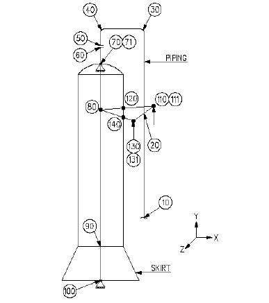 |
| Fig.2:PIPING & COLUMN MODELLING IN CAESAR-II |
Modeling for top nozzle connection
As shown in
Fig.2, piping is connected at column top nozzle. Column can be modeled by either rigid modeling or by using pipe element with
actual dimensions. Let’s start
modeling from line to column. Rest support from column is modeled at last.
1. Enter all pipe properties in CAESAR-II
spread sheet. Model node 10 to 20 as pipe element in +Y direction. At node 20
trunnion support is located, which can be modeled as described in later step.
2. Model node 20 to 30 in “+Y “direction.
Define bend at node 30.
3. Model node 30 to 40 in “–X “direction.
Define bend at node 40.
4. Model node 40 to 50 in “-Y “direction.
Model flange connection from node 50 to as rigid element and enter weight of flanges.
5. Model node 60 to 70 in “-Y” direction.
This is nozzle stand out distance from column. At the location of column and
nozzle junction, it requires to check nozzle load (axial force and moment) due
to piping reaction. To obtain this, enter “ANCHOR” restraint at node 70 with
“C-NODE” as 71.
6. Column modeling start after node 71.
Model node 71 to 80 with diameter and thickness of column. Node 80 and node 20
should have same elevation. This node is required to model rest support which
is taken from vessel. Enter correct column material, operating and design
temperature from the vendor drawing. Column can also be modeled as rigid
element.
7. Model node 80 to 90 in “-Y” direction
with length up to column bottom tan line. This element should be divided in
number of elements to enter temperature gradient profile and to consider effect
of varying thickness at different zones. Column is having different operating
temperature at different zones. To simulate actual condition, column must be
modeled with “OPERATING TEMPERATURE GRADIENT PROFILE”.
8. Model node 90 to 100 in “-Y” direction
with length of column skirt. Calculate the skirt temperature by using REAL
excel sheet of “SKIRT TEMP CALCULATION”.For skirt modeling use
skirt diameter and wall thickness. This finish the column modeling.
9. Modeling of clit support taken from
vessel: Model trunnion support from node 20 to 110 as pipe element with
diameter and thickness of trunnion. Provide ambient temperature for this
element. Enter “+Y” restraint and friction factor 0.3 at node 110 with “C-NODE”
111. Now model element from 111 to 120 with ambient temperature as rigid
element. Length and orientation should be such that it can touch to column
periphery. Model element from 120 to 80 as rigid element with diameter and
thickness equal to column diameter and thickness value. It should have same
temperature of column.
10.Similarly, model other trunnion with
node no 20-130-131-140-80.
 |
Column in
CAESAR-II Model and 3D Model
|
Links For Reference;
- Stress Analysis of Column Piping System – 01
- Stress Analysis of Column Piping System – 02
- Skirt Temperature/Expansion Calculation


4 Comments
Nice blog. Keep it up!
ReplyDeleteThanks for Your valuable feedback.
DeleteVery much useful
ReplyDeleteThanks for Your valuable feedback.
DeletePlease do not enter any spam link in comment box