
 |
| Procedure for Pump Line Analysis |
The analysis of pump-connected piping systems is considered very critical. In this article, I will try to elaborate on the method followed for the stress analysis of a centrifugal pump piping system
REQUIRED DOCUMENTS
Following Listed basic documents are required to perform stress analysis of Pump Connected System.
- Pump line Isometrics,
- Pump vendor drawing,
- Allowable nozzle Load,
- P& ID,.
PUMP MODELING
IN CAESAR-II
- End suction – Top discharge
- Top suction – Top discharge
- Side suction – Side discharge
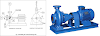
1. End suction – Top discharge
Referring to Fig.1, node marking 1-2 shows nozzle
flange with given flange rating as “rigid” element.
Node 2-3 shows nozzle standby with pipe element (Diameter equal to pump impeller diameter and thickness equal
to pipe wall thickness) as rigid element with
zero weight from flange welding
joint to pump impeller center line.
Restraints –
- The pipe flange to be get anchored as C- Node with pump flange to get nozzle load due to piping reaction. This load value should be less than allowable values.
- Rigid element at Impeller C/L to be get anchored i.e. anchor at node3.
 |
| Fig.1 |
 | |
|
2. Top suction – Top discharge & 3. Side suction – Side discharge
Referring to Fig.2 & 3, node marking 1-2 shows
nozzle flange with given flange rating
as “rigid” element. Node 2-3 shows nozzle standby with pipe element (Diameter equal to pump impeller diameter and thickness equal
to pipe wall thickness) as rigid element with
zero weight from flange
welding joint to pump impeller center line. Node 3-4 shows rigid element with zero weight up to center line of the pump.
Restraints –
- The pipe flange to be get anchored as C- Node with pump flange to get nozzle load due to piping reaction. This load value should be less than allowable values.
- Rigid element at pump C/L to be get anchored i.e. anchor at node
 |
| Fig.2 : Top suction – Top discharge |
 |
| Fig.3 : Side suction – Side discharge |
 |
| Pump with Top Suction & Top Discharge |
 |
| Pump with Side Suction & Side Discharge |
LOAD CASES FOR PUMP LINE STRESS ANALYSIS
1. Hot Cold Load case:
When two or more pumps are used in a system then from stress analysis point of view the different load cases are made. Like,
Ø
Both pump operating.
Ø
One pump pump operating & one stand by.(This point to be get discussed with process, what will be the requirement, whether “at any moment only one pump will operate, for more than two pump case”)
Ø
Hot Cold analysis to be done at design and operating temperature.
Ø
For the pump, which is not operating, ambient temperature should be considered from Tee point
Ø
When two pumps are present in the system hot cold cases can be made as below (Refer Fig. 4).

CASE 1 : When both pumps are in operating condition, provide design and operating temperature for node 10-20-30-40-A & 20-50-60-B
CASE 2 : When pump “A” is operating
and pump “B” is cold, provide design and operating temperature for node
10-20-30-40-A and ambient temperature for 20-50-60- B.
CASE 3 : When pump “B” is operating
and pump “A” is cold, provide design and operating temperature for node
10-20-50-60-B and ambient temperature for 20-30-40- A.
Ø When three pumps are present in the system hot cold cases can be made as below (Refer Fig. 5).
 |
| Fig. 5 : Pipe connected to three pump |
Case 1: When three pumps are
in operating condition, provide design and operating temperature for whole system.
Case 2: When pump “A” is cold
and pump “B & C” are operating, provide design and operating temperature to node 10-20-30-70-B & 20-50-60-C and
ambient temperature for 30-40-80-A.
Case 3: When pump “B” is cold
and pump “A & C” are operating, provide design and operating temperature to node 10-20-30-40-80-A & 20-50-60-C and ambient temperature for 30-70-B
Case 4: When pump “C” is cold
and pump “A & B” are operating, provide design and operating temperature to node 10-20-30-40-80-A & 30-70-B and
ambient temperature for 20-50-60-C.
2. WNC (Weight No Content) Load case:
The basic philosophy for “WNC” is by what magnitude the piping flange displaced
at the mating point while cold alignment. For
“WNC” case, make the pump flange anchor
node free and replace the spring support
to rigid support.
Go in load case spread
sheet, drag the “WNC” from side menu to load case row and select “Sustain case”. Run the case and get the
displacement at the pump nozzles, this displacement should be less than 1mm (or consult
mechanical department to get allowable deflection).
3. Load Cases in CAESAR-II for two pump connected system
Load cases for stress analysis
of two pump connected piping system are discussed
below. Same philosophy is applicable for more than two pump connected system.
Abbreviation: W = Weight; T= Temperature; HP = Hydro
Pressure; WW = Water Filled Weight;
WNC = Weight No Contents; P = Design Pressure. U1 = Uniform load (NS Seismic); U2 = Uniform
load (NS Seismic);
A. Load Cases for Static Analysis (Two Pumps A & B)
CASE1: WW+HP (HYD)
CASE2: W+P1+T1 (OPE) ………Both pumps at design temperature.
CASE3: W+P1+T2 (OPE) ………Both pumps at operating temperature.
CASE4: W+P1+T3 (OPE)
………Pump “A” at design temp and Pump “B” standby.
CASE5: W+P1+T4 (OPE)
………Pump “B” at design temp and Pump “A” standby.
CASE6: W+P1+T5 (OPE) ………Pump “A” at operating temp & Pump
“B” standby.
CASE7: W+P1+T6 (OPE) ………Pump “B” at operating temp & Pump
“A” standby.
CASE8: W+P1 (SUS)
CASE9: WNC (SUS)
CASE10: L2-L8 (EXP)
CASE11: L3-L8 (EXP)
CASE12: L4-L8 (EXP)
CASE13: L5-L8 (EXP)
CASE14: L6-L8 (EXP)
CASE15: L7-L8 (EXP)
- For load case no 2, 3, 4, 5, 6,7and 8 pump nozzle load is checked and it should be within acceptable limit as specified by vendor or API 610.
- For load case no 1, 8, 10, 11,12,13,14 and 15 stress value is checked and it should be less than allowable stress as specified by relevant code.
- For load case no 9 (WNC case) deflection is checked at pipe flange for cold alignment case as discussed in earlier topic of WNC load case.
B. Load Cases for Static Analysis (Three Pumps A, B & C)
CASE1: WW+HP (HYD)
CASE2: W+P1+T1 (OPE) …Three pumps at design temperature.
CASE3: W+P1+T2 (OPE) …Three pumps at operating temperature.
CASE4: W+P1+T3 (OPE) ….Pump “B&C” at design temp and
Pump “A” standby.
CASE5: W+P1+T4 (OPE) …..Pump “A&C” at design temp and
Pump “B” standby.
CASE6: W+P1+T5 (OPE) …..Pump “A&B” at design temp and
Pump “C” standby.
CASE7: W+P1+T6 (OPE) …..Pump “B&C” at operating temp and
Pump “A” standby.
CASE8: W+P1+T7 (OPE) …..Pump “A&C” at operating temp and
Pump “B” standby.
CASE9: W+P1+T8 (OPE) …..Pump “A&B” at operating temp and
Pump “C” standby.
CASE10: W+P1 (SUS)
CASE11: WNC (SUS)
CASE12: L2-L10 (EXP)
CASE13: L3-L10 (EXP)
CASE14: L4-L10 (EXP)
CASE15: L5-L10 (EXP)
CASE16: L6-L10 (EXP)
CASE17: L7-L10 (EXP)
CASE18: L8-L10 (EXP)
CASE19: L9-L10 (EXP)
- For load case no 2, 3, 4, 5, 6, 7, 8, 9 and 10, pump nozzle load is checked and it should
be within acceptable
limit as specified by vendor or API 610.
- For load case no 1, 10, 12, 13, 14, 15, 16, 17, 18 and 19 stress value is checked and it should be
less than allowable stress as specified by relevant code.
- For load case no 11 (WNC case) deflection is checked at pipe flange
for cold alignment case as discussed in earlier topic of
WNC load case.
C. Load Cases for Seismic Analysis:
Replace all “+Y” restraint by “Y” restraint. Remove all friction and guide gap at restraints. Click on uniform load in CAESAR spread sheet and enter 0.34 value in UX and UZ direction.
Activate uniform load in G’s option in Kaux – special execution
parameters. Make load cases as below:
CASE2: U1 (OCC)
CASE3: U2 (OCC)
CASE4: L1+L2 (OCC)
CASE5: L1+L3 (OCC)


0 Comments
Please do not enter any spam link in comment box