
The Purpose for preparing this Blog is, to understand the methods of Pump modeling in Caesar-II for various configurations of pumps. Also, to understand inputting of temp. /press. Profiles, when number of pumps used in a single system. This Blog helps in studying various scenarios & cases of pumps.
REQUIRED DOCUMENTS:
- Pump vendor drawing.
- Pump Line isometric.
- P & ID for the line.
PUMP MODELING IN CAESAR-II
- End suction – Top discharge
- Top suction – Top discharge
- Side suction – Side discharge
A. End suction – Top discharge:
1- A) When discharge nozzle is on shaft center-line:
 |
Discharge nozzle is on shaft center-line |

21-30 : Model Node 21-30 as rigid element with zero weight (diameter approximately equal to pump casing diameter and thickness equal to pipe wall thickness) to node 30.Define Anchor at node 30 i.e. at fixed point.
1- B) When discharge nozzle is off-set with shaft center-line:
Modeling of Discharge side (REFER FIG 1b).
 |
| Discharge nozzle is off-set with shaft center-line |
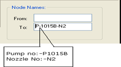
10-20 : Model Node 10-20 as rigid element & input
flange weight (piping side flange) w.r.t flange rating. Define restraint
i.e. Anchor at Node 20 with C-Node 21 to get the loads of
pump nozzle due to piping reactions. This load value should be less than
allowable values. Also, define Pump name, nozzle
name/type in the node name field in ‘TO’ tab.
21-30 : Model Node 21-30 as rigid element with
zero weight (diameter approximately equal to pump casing diameter and thickness
equal to pipe wall thickness) to node 30.
30-40 : Model 30-40 as rigid element with pipe properties same as for node 21-30, from offset point of discharge nozzle (node 30), to node 40, with distance ‘d1’.Define Anchor at node 40 i.e. at Fixed point.
For suction side modeling procedure is same as given in 1-A, (refer FIG. 1a).
B. Top suction – Top discharge:
2-A) When nozzles are on shaft center-line:
Modeling of
Suction & Discharge side (REFER FIG 2a).
 |
| Top Suction-Top Discharge nozzle, nozzle are on shaft center line |
10-20 : Model Node 10-20 as rigid element & input
flange weight (piping side flange) w.r.t flange rating. Define restraint i.e.
Anchor at Node 20 with C- Node 21 to get the loads of pump nozzle due to piping
reactions. This load value should be less than allowable values. Also, define
Pump name, nozzle name/type in the node name field, in ‘TO’ tab.
21-30 : Model Node 21-30 as rigid element with zero
weight (diameter approximately equal to pump casing diameter and thickness
equal to pipe wall thickness) to offset point of discharge nozzle (node 30).
30-40 : Model 30-40 as rigid element with zero weight.
Pipe properties are same as for node 21-30, with distance ‘d/2’ .Define Anchor
at node 40 i.e. at fixed point. Refer NOTE-1 given below.
 |
| Top Suction-Top Discharge nozzle, nozzle are on shaft center line |
NOTE-1: - For above type of pumps, fixed point is assumed exactly at center of distance between suction & discharge nozzle. Such type of modeling can be use only at preliminary stages of the projects, when data such as displacements of nozzles from fixed point or anchor location is not available. Stress-Analyst should ask the vendor for the displacement value of each nozzle before AFC.
2-B) When nozzles are off-set with shaft center-line:
Modeling of
Suction/Discharge side (REFER FIG 2b).
 |
| Top Suction-Top Discharge nozzle, nozzle are off-set with shaft center line |
10-20 : Model Node 10-20 as rigid element & input flange weight (piping side flange) w.r.t flange rating. Define restraint i.e. Anchor at Node 20 with C-Node 21 to get the loads of pump nozzle due to piping reactions. This load value should be less than allowable values. Also, define Pump name, nozzle name/type in the node name field in ‘TO’ tab.
21-30 : Model Node 21-30 as rigid element with zero
weight (diameter approximately equal to pump casing diameter and thickness
equal to pipe wall thickness) to node 30.
30-40 : Model 30-40 as rigid element with pipe properties same as for node 21-30, from offset point of discharge nozzle (node 30), to node 40, with distance ‘d1’ for suction and ‘d2’ for discharge side. Define Anchor at node 40 i.e. at fixed point.
 |
| Top Suction-Top Discharge nozzle, nozzle are off-set with shaft center line |
2-C) When nozzles are off-set with each other & shaft center line:
Modeling of
Suction/discharge side (REFER FIG 2c).
 |
| Top Suction-Top Discharge nozzle, nozzle are off set with each other & shaft center line |
10-20 : Model Node 10-20 as rigid element & input nozzle flange weight w.r.t flange rating. Define restraint i.e. Anchor at Node 20 with C-Node 21 to get the loads of pump nozzle due to piping reactions. This load value should be less than allowable values. Also, define Pump name, nozzle name/type in the node name field, in ‘TO’ tab.
21-30 : Model Node 21-30 as rigid element with zero
weight (diameter approximately equal to pump casing diameter and thickness
equal to pipe wall thickness) offset point of discharge nozzle node 30 with
pump shaft center line.
30-40 : Model 30-40 as rigid element, with pipe
properties same as node 21-30, from offset point of discharge nozzle (node 30)
to node 40, with distance ‘d1’ for suction and ‘d2’ for discharge
side.
40-50 : Model 40-50 as rigid element, with same pipe properties as node 21-30, from intersection point of nozzle line to shaft center line (node 40), to node 50,with distance ‘d3/2’. Define Anchor at node 50 i.e. a Fixed Point.
 |
| Top Suction-Top Discharge nozzle, nozzle are off set with each other & shaft center line |
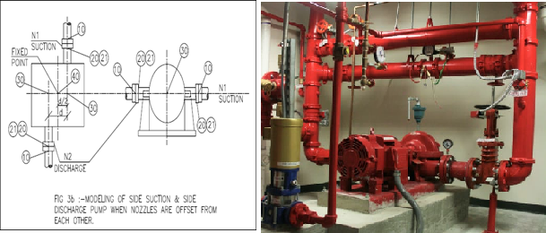
C. Side suction – Side discharge:
3-A) When nozzles are in-line with each other:
Modeling of Suction/Discharge side (REFFERING FIG 3a).
 |
| Side Suction-Side Discharge nozzle, nozzle are in-line with each other |
For modeling of suction/discharge side of pump, refer
modeling procedure given for End suction Top discharge pump in 1 .A, with REFER
Fig 3a given below.
 |
| Side Suction-Side Discharge nozzle, nozzle are in-line with each other |
3-B) Modeling of Suction/Discharge side:
When nozzles are
offset with each other (REFER fig 3b).
 |
| Side Suction-Side Discharge nozzle, nozzle are offset with each other |
10-20 : Model Node 10-20 as rigid element & input
flange weight (piping side flange) w.r.t flange rating. Define restraint i.e.
Anchor at Node 20 with C-Node 21 to get the loads of pump nozzle due to piping
reactions. This load value should be less than allowable values. Also, define
Pump name, nozzle name/type in the node name field.
21-30 : Model Node 21-30 as rigid element with zero
weight (diameter approximately equal to
pump casing diameter and thickness equal to pipe wall thickness) to offset point
of discharge nozzle (node 30).
30-40 : Model 30-40 as rigid element with pipe
properties same as for node 21-30, with distance ‘d/2’.Define Anchor
at node 40 i.e. at fixed point. Refer NOTE-1 given in 2-A.
 |
| Side Suction-Side Discharge nozzle, nozzle are offset with each other |
TEMPERATURE/PRESSURE PROFILES USED WHILE ANALYSIS:
Load cases for the pump connected lines are discussed
below.
INPUTTING OF TEMPEARTURE & PRESSURE PROFILE FOR THE
PUMP SYSTEM:
When two or more pumps are used in a system then from stress analysis point of view the different load cases are made. Like,
- All pump operating.
- Operating & stand by philosophy of Pumps.
This
point should be discussed with Process dept. before preliminary analysis,
regarding operating & stand-by philosophy for two pumps, operating &
stand-by philosophy for three or more pumps, steam-out philosophy, etc. Load
cases to be made at operating temperature, design temperature and steam-out
temperature (If required from process/vendor).
For the pump, which is not operating, ambient/base
temperature should be considered from shut-off valve flange.
A) When two pumps are present in the system:
Inputting
for temperature & pressure can be made as shown below Fig. 4a.

Case 1: When both pumps are in operating condition, input design and operating temperature/pressure from node 10-20-30-40-50-PUMP-A & 10-60-70-80- PUMP-B.
Case 2: When pump “A” is operating and
pump “B” is stand-by, input design and operating
temperature/pressure for node 10-20-30-40-50- PUMP-A, from 10-60-70 up to
shut-off valve flange and input base temperature/pressure from node
70-80-90-PUMP-B.
Case 3: When pump “B” is operating and pump “A” is stand-by; input design and operating temperature/pressure from node 10-60-70-80-PUMP-B, from node 10-20-30 up to shut-off valve flange and input base temperature/pressure from 30- 40-50-PUMP-A.
B) When three pumps are present in the system:
Inputting
for temperature & pressure can be made as shown below Fig.
Case1: When three pumps are in operating condition, input design and operating
temperature/pressure for whole system.

Case 2: When pump “A & B” are operating
and pump “C” is stand-by, input design and operating
temperature/pressure from node 10-20-30-40-50-PUMP-A, from 10-60-70-80-PUMP-B
and from node 10-90-100 up to shut-off valve flange. Input ambient
temperature/pressure for 100-110-120-PUMP-C.

Case 3: When pump “A & C” are operating
and pump “B” is stand-by, input design and operating
temperature/pressure from node 10-20-30-40-50-PUMP-A, from node
10-90-100-110-120-PUMP-C, from node10-60 up to valve flange and input ambient
temperature/pressure for 60-70-80-PUMP-B.
Case 4: When pump “B & C” are operating
and pump “A” is stand-by, input design and operating
temperature/pressure from node 10-60-70-80-PUPM-B, from node
10-90-100-110-120-PUMP-C, from node 10-20-30 up to shut-off valve flange and
input base temperature/pressure for 30-40-50-PUMP-A.

WNC (Weight No Content) Load case:
The basic philosophy for “WNC” is to find out the magnitude of the piping flange displacement at the mating point before cold alignment.
For “WNC” case, make the
pump flange anchor node free and replace the spring support to rigid support. Some Companies while performing WNC, keep the spring support as design.
Procedure for defining WNC case:-
1.Go in load case spread sheet.

2.Drag the “WNC” from side menu to load case row.
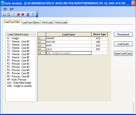
3.Select “Sustain case”.

Run the case and get the displacement at the pump nozzles,
this displacement should be less allowable displacement asper API RP 686 or less than 2mm (Should be inline with Project Design Bases) or consult mechanical department to
get allowable deflection.
Links for Reference articles:
- Stress Analysis Of Column Piping System–02
- Skirt Temperature/Expansion Calculation
- Piping & Column Modeling in CAESAR-II
- Procedure for Pump Line Analysis


0 Comments
Please do not enter any spam link in comment box