Magnetic Particle Applications
Prior to discussing the applications, some previously mentioned principles are recapped below. several different bases are used for classifying magnetizing methods:
- Whether or not the magnetizing force is maintained during the application of the medium. This includes the residual and continuous methods.
- The character of the field utilized for magnetization which includes the circular and longitudinal methods.
- The type of magnetizing current used which may be either AC, DC, or HWDC.
Residual Method
The medium is applied after the specimen has been magnetized and the magnetizing force removed. This method is not used on specimens that have low Retentivity.
Continuous Method-
The magnetizing operation is conducted simultaneously with the application of the Dry Powder or Wet Suspension.
Circular Magnetization Procedures
Where it is necessary to pass a current through the
specimen, care must be exercised to prevent arcing or overheating at the
contact areas. All contact areas must be clean, and suitable head pressure must
be exerted to insure uniform magnetization.
Longitudinal Magnetization Procedures
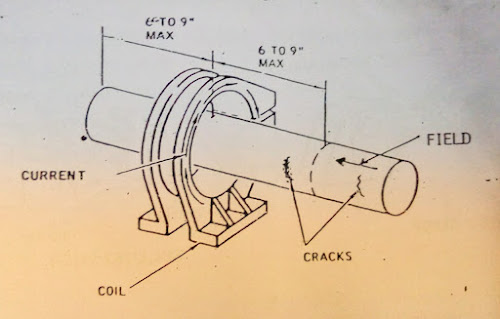
When a solenoid or coil is used to magnetize the specimen, it should be no larger than necessary to accommodate the specimen.
Direct Current : To obtain indications of discontinuities that may be subsurface, Direct current (DC) or halfwave rectified current (HWDC) should be used.
Alternating Current : AC is used when the discontinuities are suspected to
be on the surface of the specimen.
Testing Medium (Powders and Suspensions)
Dry Powder is
commonly used for testing weldments where the prod method is employed. The
powder is sprinkled on the surface while the magnetizing current is flowing.
Liquid medium (Non-Fluorescent) can be used with both wet residual and wet
continuous methods.
Liquid Medium(Fluorescent) can also be used with both wet residual and wet continuous methods. The particles are coated with a fluorescent dye which, when inspected under a black light, fluoresce brilliantly.
The Bath Strength can be checked by the settling test described in last blog,Magnetic Particle Testing -X: Magnetic Particle Mediums & Preparation. The frequency of the test is determined by the degree of bath usage with the strength usually dependent upon the manufactures’ specifications.
Surface Preparation
Prior to magnetic particle testing, the specimen should be thoroughly cleaned. Cleaning may involve removal of flake, slag, heavy build-up of paint, test results. The smoother the surface and the more uniform the color, the more favorable are the conditions for formation of a magnetic particle indication.
Location of Discontinuities
Discontinuities can be located either on or directly below the surface of the specimen. Discontinuities located on the surface appear as sharp, distinct lines, whereas, discontinuities located below the surface appear as irregular, rough, hazy indications.
Demagnetization Requirements
If a specimen is to be magnetized in a second direction, I. e. circular magnetization followed by longitudinal magnetization, the last applied field will drive out the residual field from the preceding magnetization. However, this will happen only if the magnetizing force last applied is equal to or higher than the previous residual field.
A Field Indicator is used after performing demagnetization on an article that has been circularly magnetized to Demagnetize if the field strength is reduced to the desired level. Large specimens can be found difficult to demagnetize completely. shifting the specimen to align it in an east-west position from an original north-south position facilitates demagnetization. The reason for this is the influence of the earth’s magnetic field.
Application of MPT Procedures
The magnetic particle technician must have a good
understanding of the reasons for applying the different techniques to the same
part. It is even more important to be able to select the proper technique and
procedure to obtain the best results.
Magnetization of A Solid Cylindrical Specimen
What methods must be used to find all of the discontinuities shown in the bar below?
Head Shot (Circular Magnetization): Inspect for discontinuities showing a longitudinal indication.
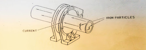
Coil Shot (Longitudinal Magnetization): Inspect for transverse indications.
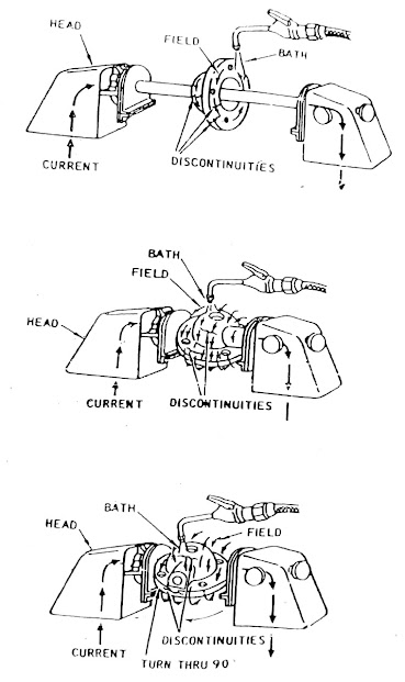
Magnetization of A Large Gear
What method must be used to find all of the discontinuities in the gear below?
Head Shot (Circular Magnetization) with central conductor: Inspect for discontinuities perpendicular to the circular field.
Head Shot (Circular Magnetization) using at least two shots and turning the gear 90 degree.
Magnetization of Short Hollow Cylinders
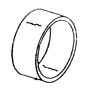
What methods must be used to find the discontinuities on the inside and outside of this ring?
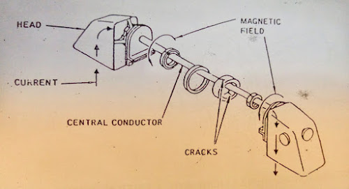
Head Shot (Circular Magnetization) with central conductor
If necessary, the ring can also be magnetized by two head shots across the diameter or by placing in a coil. This will produce a longitudinal field which will detect discontinuities in the direction shown below.
Magnetization of Hollow Cylindrical Specimens
What method
must be used to find the discontinuities on the inside and outside of this
cylinder?
Coil Shot (Longitudinal Magnetization): Inspect for discontinuities showing transverse indications on the inside and outside of the cylinder as shown below.
Head Shot (Circular Magnetization) with central conductor: Inspect for longitudinal discontinuities on the inside and outside of the cylinder as shown below.
Magnetization of Irregularly Shaped Specimens
Each specimen must be thoroughly analyzed to determine which methods will be necessary to find discontinuities in all directions. the part shown below requires the use of a central conductor and two additional head shots.
Magnetization of Large Weldments or Castings
Circular magnetization of large specimens is usually accomplished with the use of Prods. Longitudinal magnetization of large specimen is usually done with either a Yoke or by Wrapping the part with the cables.
The Weldment shown below requires a crisscrossed pattern in applying the magnetizing current with prods to insure 100 percent coverage of discontinuities.
The large shaft shown below requires the cables to be wrapped at several different locations to insure 100 percent coverage. However, longitudinal discontinuities will not be detected with this method.









0 Comments
Please do not enter any spam link in comment box