Circular Magnetization
A circular magnetic field is induced into a specimen by:
Direct induction of a circular field into an article. This is accomplished by, passing a current through the article as shown in the head shot below.
Direct induction using prods-prod magnetization is used where the size or location of an article does not permit the use of a head shot or location of an article conductor. Current flow and circular field distributions are shown below.
Indirect induction of a circular field. This is accomplished by placing a current-carrying conductor into the specimen. This method is known as the central conductor technique and is illustrates below.
Circular magnetic field in a nonmagnetic material
In a nonmagnetic material the lines of force will not stay in the material for example, when a copper bar is used, the magnetic field is established around the bar as shown below.
Circular magnetic field in a ferromagnetic material
In a ferromagnetic material the lines of force are established within the material. Iron is permeable and readily conducts the magnetic field as shown below.
In both ferromagnetic and nonmagnetic materials. The lines of force are at right angles (90 Deg) to the direction of electric current flow. Iron particles will not be attracted to a magnetized part except where a flux leakage exists. A crack in the part as shown below. would cause a typical indication.
Circular magnetization will detect discontinuities that are between 45 and 90 degrees, to the lines of force. A crack that runs parallel to the lines of force will not attract particles because no poles or flux leakage exists at the crack (see below).
The circular
magnetization created with prods will also only detect discontinuities that are
essentially perpendicular to the lines of force.
Longitudinal magnetization
A longitudinal magnetic field is induced into a specimen by:
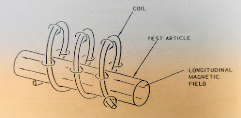
coil (solenoid)- when the length of the specimen is several times its diameter or cross section, the specimen can be successfully magnetized by placing it lengthwise in the field of the coil (see below).
Yoke- a yoke may be used to magnetize a specimen longitudinally as shown below. The yoke is essentially a temporary horseshoe magnet. It is made of soft. Low retentivity iron. Which is magnetized by a small coil wound around its horizontal bar.
Note: both illustrations above use the older convention (+to-using the right-hand rule) to demonstrate current flow. When copper wire is wound into a coil, the lines of flux around each turn of the coil
This
increases the flux density in the longitudinal direction.
The flux density is the greatest at the surface of the copper wire; Therefore, flux density will be greatest at the inside surface of the coil.
Parts being
magnetized should be placed near the inside surface of the coil as shown below.
Which of the discontinuities
on the surface of the bar on the right would be detected if it were inspected
in the coil on the left?
Few more piping resources ...


0 Comments
Please do not enter any spam link in comment box